Immersion Heater Products & Design Considerations
Last updated on November 6th, 2024 at 01:17 pm
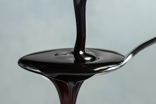
 “As slow as molasses in January” is a classic Americanism. It references the agonizing slowness found in government, management, and even molasses.
Many industries rely on the flow of viscous fluids. The proper application of immersion heating dramatically enhances the behavior of process fluids. This is as true in a trans-Alaskan oil pipeline as in a honey dispenser at the grocery. The regulation of flow is important in all sorts of processes.
There is also a wide application of immersion heating elements in water. There are common design principles across all sorts of applications. From pressurized-water nuclear reactors to the water heater in a home.
In this article, we explore some of the basic thermophysics that govern the design of immersion heating elements. This can aid in selecting heater products and consideration of major design trades.
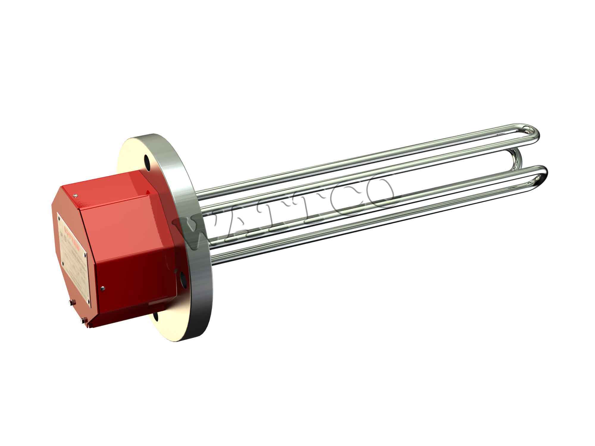
Immersion Heater Definition
What defines an immersion heater? After all, common electric-coil furnace elements are immersed in air. This discussion concerns itself with the adverse effects of improper heater design and fluid pairing.
 In particular, this relates to a phase change or reaction in a fluid. What does that look like in practice?
The heating of molasses must avoid scorching the molasses. Heating of water must avoid boiling beyond the design tolerance of the water system. Heating of oil must avoid charring or igniting the oil.
In the above cases, the surface temperature of the heater element is the variable that must be controlled to avoid adverse outcomes.
Heater burnout is always a risk, no matter the fluid involved. And one must mitigate this risk in all circumstances. However, for a typical immersion heater configuration, the adverse alteration of the process fluid occurs at a lower temperature than heater burnout. Nuclear reactor fuel rods are a notable, but highly specialized, exception.
Risk Management
For safe and efficient processes, managing risks is essential.
Heater failure is a feed-forward process. As char accumulates on the surface, the temperature of the surface rises. This allows more char to form, forcing the temperature higher. Left unchecked, the issue worsens exponentially.
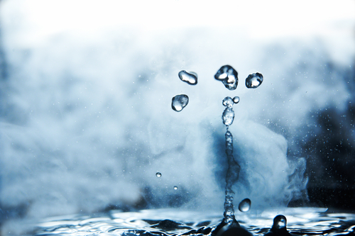
In water, if boiling departs from the stable nucleate regime, vapor near the surface will cause rapid elevation of the surface temperature. This due to poor heat transfer through the vapor phase. This compromises heater performance. In the case of some process fluids and systems, a hazardous condition may develop if heater temperatures approach autoignition of the fluid, or vapor generation causes the system pressure to rise.
In food processes, overheating can cause undesirable tastes and odors. Understanding more about the thermal-fluid processes can help manage risk.
No-Slip Walls
One of the basic axioms of fluid mechanics is the no-slip wall. The layer of fluid in contact with the heated surface is assumed to be bonded there. Therefore, it would be in thermal equilibrium with the surface.
 A boiling fluid experiences dry-out and rewetting. So the surface is not in equilibrium with the first fluid layer. Statistical mechanics gives perspective to this process by introducing the concept of residence time. This is where fluid molecules, rather than the continuous bulk fluid, are thought of as stuck to the wall for some finite period. This period is shorter for hotter walls or smaller molecules. The period is longer for cooler walls and larger molecules.
If boiling is occurring, there is a probability that a given molecule will arrive in the liquid phase and depart in the vapor phase. If charring is the risk, then the molecule may arrive as a liquid and remain bonded as a solid. Both of these cases increase the resistance to heat flux. Which along with its inverse, the overall heat transfer coefficient, can be a very convenient metric to allow comparisons of very dissimilar systems.
Source & Sink
Heat must flow from a source to a sink. For immersion heaters, that means from the resistance element to the bulk fluid. Between the source and sink, several heat transfer processes can impede heat flow.
Internal to the heater resistance element, there is a conduction term that governs how the dissipated power moves to the surface of the element. Meaning that the centerline of the element is hotter than the perimeter.
Internal to the heater, there may be some bonding between the electric element and the sheathing of the heater. Which is selected to avoid chemical interactions with the process fluid. And thus the interior of this bond region is hotter than the inner surface of the sheath. This term may be conductive or may include radiation if there is a gap between element and sheath.
Further, the sheath has some thickness to it. This may be a function of the pressure at which the heater must operate. And the inside of the sheath will be hotter than the outside.
Finally, the fluid is cooler than the heater. The convection term captures the temperature rise required to drive a certain heat flux from the outer surface of the sheath into the fluid. The analogy of electrical resistors can help one understand thermal resistance.
Each of these links in the chain acts as a resistor in series. Together, they add up to some total thermal resistance to heat flux. We measure this in degrees per heat flux, typically square meters Centigrade per Watt. The inverse of this is the overall heat transfer coefficient.
Terms
Clarity in terms is critical. A flux is a flow-through an area. This allows meaningful comparison of heater behavior from the large to the small scale by comparing the allowable heat flux for a fluid-surface pair. Given similar fluid flow regimes, engineers can make decisions that apply to a process vat or a bench-top apparatus.
How can fluid flow regimes be compared?
Where flow is forced by a pump, fan, or another external source, the dimensionless Reynolds number shows the ratio of momentum to viscosity. Similar behavior is expected from flows of similar Reynolds number.
The heating of oil in a transport pipeline is a meaningful example of a forced flow. The pipeline branches of different diameters, flow rates, and temperatures. These can be compared based on the Reynolds number.
In the case of heating a quiescent fluid, momentum is not supplied externally. Rather, it’s generated by buoyancy resulting from thermally induced density changes. The near-heater fluid is warmer. And as most materials and fluids expand when heated, this warmer fluid rises through the surrounding cooler fluid. This creates convection currents.
The closely related dimensionless Rayleigh or Grashof numbers allow meaningful comparison between these buoyancy forces and the countervailing viscous forces.
The appropriate dimensionless fluid parameter is a key term in convective heat transfer, as more motion of the fluid will promote better heat rejection from the immersed heater. This is one of the thermal resistances bundled up into the overall heat transfer coefficient. And for many heaters, especially those in viscous process fluids, convection is the limiting factor in heat transfer.
Temperature Difference
Without a driving temperature difference, there will be no heat leaving the heater. This gradient is established by the electric power spent in the immersion heater. The peak temperature internal to the heater is determined by this power. As well as by the thermal resistance between the heater and the bulk fluid.
This overall heat transfer resistance is the key consideration in sizing an immersion heater for a given fluid with a known maximum permissible temperature. If this resistance is high, the designer may require a lower heat flux, meaning a larger heater or a lower power. Moreover, most process engineering components are subject to degradation by time and service.
Mineral fouling of water heaters is the most commonly encountered example. But the concern is not limited to water systems.
Thus, the designer must consider the predicted end-of-life heater surface temperature, not simply the desired bulk process temperature. This allows them to select a safe and suitable immersion heater system.
